EVALUATION of MULTI-SECTION COMPRESSORS
Field testing Process Compressors is not a simple task, but the proper procedures and tools simplify the project. Accurate data and proper analysis is necessary to compare operating data to the manufacturer's guarantee and confirm that you got what you paid for. Proper analysis is required to justify a project whether it be new equipment, a rerate, or an overhaul. Frequent and regular testing is essential to monitor operating expenses and to aid in determining overhaul frequency.
The field test check list:
- A method of obtaining accurate pressure and temperature at each compressor flange. "Snapshot" data is preferable to minimize the effects of transients.
- A means of calculating the mass flow rate to the compressor. This is generally done with an orifice plate or nozzle.
- Vane setting for variable inlet vane units.
- Gas analysis via. Gas Chromatograph.
- A compressor performance program that utilizes BWR equations of state.
- Driver power.
- Compressor and driver mechanical losses.
- Manufacturers Performance Curves
- Speed
Iso-Cooled Compressors
Field testing Iso-cooled compressors can be straight forward, but a few precautions are in order. Treat each section of the machine like a separate single section compressor but keep the following items in mind.
Gas Analysis
Process gas flowing to the second section of the compressor may, due to the gas composition, be different than the first. Liquids may form in the cooler and be drained out prior to continuing on to the next section. Flow to the second section thus will have a lower mass flow rate and the gas will have a lower mole weight. This is especially true for installations like wet (rich) gas compressors.
Measuring the flow of liquid flowing from the cooler and the process gas flow at the compressor main inlet (or discharge) will provide the mass flow rate for the other section by subtracting (or adding) .
Be sure to follow proper precautions when taking a gas sample. Condensate can form on the gas sample container walls and give erroneous results unless proper procedures are followed. Make sure you confirm values by comparing the discharge gas analysis to the inlet gas analysis for the same section. The accuracy of your test results are no better than the agreement between your gas analysis results.
Heat Transfer
Heat conduction from the discharge of the first section to the next section inlet can make results confusing. For example, assume that a compressor has a discharge temperature for the first section of 356 °F and an inlet to the second section of 90 °F. It is easy to understand that there is considerable heat flowing across the wall separating the two sections because of this high temperature differential. This heat is of course flowing from the discharge of the first section to the inlet of the second. The measured temperature at the discharge flange of the first section thus does not accurately represent the true temperature at the discharge of the last wheel of that section. Likewise, the temperature at the inlet flange to the second section does not represent the true temperature at the first impeller in the second section due to the heat transfer effect.
The first stage discharge temperature is artificially low thus a higher than actual efficiency and corresponding low power is calculated. Just the opposite is true for the second section. While this effect should be reflected in the manufacturers predicted performance values, the actual sectional performance can be difficult to accurately predict.
Seal Leakage
To fully understand the performance of Iso-cooled compressors, seal leakage must also be considered. The two areas of importance are the balance piston seal and the seal between the iso-cooled sections.
Normal seal leakage is represented in the compressor design performance. Seal degradation will affect the observed power and efficiency values.
Higher than design flow across the balance piston seal will affect the discharge temperature of the first section since the hot balance piston leakage will heat up the compressor first stage inlet gas (assuming the balance line is returned to the main inlet). Performance analysis of a compressor with a defective balance piston will thus show a higher than normal power consumption (low efficiency) for the first section. The second section will be affected slightly due to the increased discharge temperature of the first section and resulting increase in heat transfer to the second stage inlet, but usually this effect is insignificant.
If the internal seal between the two sections is damaged, increased flow across this seal will affect test results. Higher leakage from the wiped seal will increase the temperature of the second section inlet since, in the example above, the 356 °F gas (discharge of the first section) is flowing to and mixing with the 90 °F second stage inlet gas.
Compressors with Economizer Nozzles
Proper analysis of a sideload compressor requires internal temperature and pressure probes in order to properly calculate the performance of the individual sections of the compressor. This is the normal procedure in any shop proof test following the purchase of a new refrigeration compressor with economizer nozzles since this is the only way that the compressor sectional performance can be properly analyzed and compared to predicted values.
While pressure can be estimated for the mixing area by estimating the pressure drop from the sideload external measurement point to the mixing area, the internal temperature must be measured.
In a shop test environment, the installed internal probes are generally removed prior to shipping the equipment and are not available for field measurements. Where these internal data are not available, overall values for power and efficiency can be monitored.
Overall Power
The gas horsepower for a single stage compressor is:
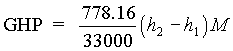 (equation 1.0)
Where:
2 = Discharge
For a sideload machine:
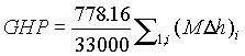 (equation 2.0)
Where:
i = the number of sections of the compressor
For a compressor with two sideloads (three sections):
![]()
(equation 3.0)
Overall Efficiency
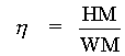
Efficiency for a compressor is defined as head divided by the work input:
 (equation 4.0)
For a multi-section compressor, an overall compressor efficiency is calculated by dividing the head from each section by the sum of the work from each section:
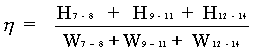 (equation 5.0)
For the case of the field sideload compressor where points 8 and 11 are not available a modified cycle is suggested for calculating overall efficiency. Internal mixing is assumed not to occur in order to simplify the solution. The system is treated as three separate and parallel flow paths with measurable end points.
For a single stage compressor:

Multiply by M/M:
For a multi-section compressor (three sections):
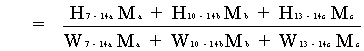
W = (D h) 778.16
 (Equation 6.0)
While this procedure may not correctly model the true polytropic process, it does give a very close approximation of the overall condition of the compressor performance.
Any error realized from using equation 6.0 in place of equation 5.0 is reduced as the main inlet flow is increased and the side stream flows are decreased
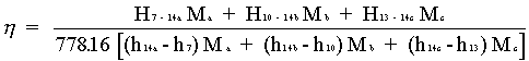
Example:
Using equation 6.0. This equation is used when only external data is available:

M a = 3258.5 #/min @ -29.4oF, 18.72 PSIA
M b = 310.3 #/min @ -6.3oF, 35.03 PSIA
M c = 1152.7 #/min @ 19.9oF, 58.55 PSIA
Mt 4721.5 #/min @ 133.8oF, 162.1 PSIA
H 7-14 = 35,188
H 10-14 = 25,518
H 13-14 = 17,126
h 14a-h 7 = 155.4-102.8 = 52.6
h 14b-h 10 = 156.5-109.5 = 47
h 14c-h 13 = 156.7-116.5 = 40.2
Note that for this example, each section has a different gas analysis. This is why h14a does not equal h14b or h14c.
![]()
![]()
= 0.7873
Using Equation #5.0. This equation is used with internal data and sectional head and work can be accurately calculated:
h = 0.796
Error = -1.2%
FIELD DATA ANALYSIS
Trend the performance data looking for any changes. To confirm accuracy of your data, compare the total compressor power to the driver power and monitor the compressor work input. Work input is a good indication of the collected data accuracy. Work input values remain constant for varying inefficiencies in the compressor. If work input is off design, then there may be instrumentation problems or something affecting the compressors ability to do work, such as flow swirl.
Setup a spread sheet and plot the manufacturers data for the compressor head and efficiency vs. flow as well as work vs. flow (see equation 4.0). Data plotted on these curves should be fan law corrected for speed differences.
Nomenclature:
a = Main Inlet
b = 1st Sidestream
c = 2nd Sidestream
t = Total, Discharge Flow
7 = Main Inlet
8 = Disch First Section
9 = Inlet Second Section
10 = 1st Sideload
11 = Disch Second Section
12 = Inlet Third Section
13 = 2nd Sideload
14 = Final Discharge
h = total enthalpy
M = Mass flow
H = Head
W = Work
h= Efficiency, Polytropic
GHP = Gas Horsepower
Kaylyn Gresh
August-97
Kaylyn K. Gresh currently holds a position as a research Analyst for Flexware, Inc. on a part time basis. Her work for Flexware includes the research and analysis of gas properties and performance analysis of turbomachinery.Ref: Field Analysis of Multi-Section Compressors, by K. K. Gresh, Hydrocarbon Processing, Jan 1998.